Concentric Flow Control (CFC) Vent Mast
A smaller, lighter, and less expensive solution for safer release of lighter-than-air flammable gases.
Gaseous or liquid hydrogen tank releases, or releases of other lighter-than-air flammable gases, are typically routed up a vent mast into ambient air, where they can safely dissipate and not return to ground level. This requires a relatively tall mast structure that can create serious concerns depending on the application. For example, mast structures can restrict a transport vessel’s clearance under bridges or other infrastructure, or create visual interference at fixed storage or dispensing locations. Typically constructed from steel, a tall vent mast can also result in weight penalties, or lead to stability problems related to a transport vessel’s vertical center of gravity.
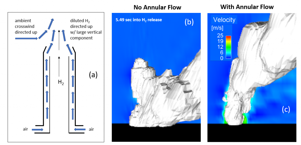
The Concentric Flow Control (CFC) Vent Mast consists of two concentric tubes, where the conventional vent mast is surrounded by another cylinder, creating an annular region between the two tubes for the flow of air or inert gas. The annular flow generated by fans or compressed gas accomplishes three independent functions: it entrains the flammable gas with more mass of inert species than would be achieved with venting into quiescent air, helping dilute the gas to below the lower flammability limit; it pushes the flammable gas by momentum-driven flow high above the mast exit, allowing for a shorter mast while maintaining safe gas dispersion; and, it overcomes cross winds or downward pointing air flow, forcing air flow to be substantially vertical, away from ignition sources, critical infrastructure, and people.
- Flammable gas dilution
- Vertical gas flow direction
- Undesirable wind effects mitigation
- Liquid Natural Gas (LNG) carriers
- Liquid Hydrogen (LH2) tankers
- Vessels using hydrogen for propulsion power
- Vessels using natural gas for propulsion power
- Fueling stations dispensing natural gas
- Hydrogen stations fueling fuel cell vehicles
- Hydrogen production plants
- Oil refineries
SD# 15963
Published6/27/2022
Last Updated1/15/2025